Step response of Quadrotor BLDC/ESC drive unit
For the design of stable and fast QR control loops knowledge about the step response of the plant is highly important.
However, almost no quantitative specifications are provided by BLDC/ESC manufacturers.
Therefore, we provide step response measurements for our QR drive unit, i.e., Lipo nVision 3s 3700mAh, ESC FVT LittleBee 20A, BLDC MT2216 810rpm/V,
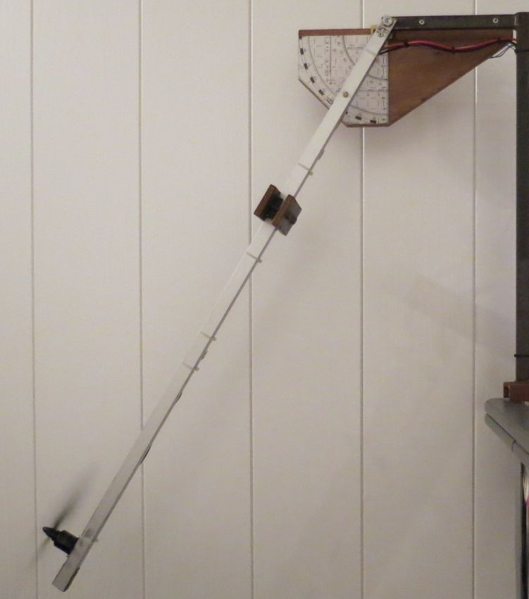
Airscrew GemFan 10x4.5". For data acquisition the testbench shown below was employed along with a 4 channel 100 MHz digital oscilloscope. The PWM set
point was chosen to match hover conditions, i.e., PWM0 = 630LSB corresponding to one quarter of the total QR mass of approximately 1250g.
|
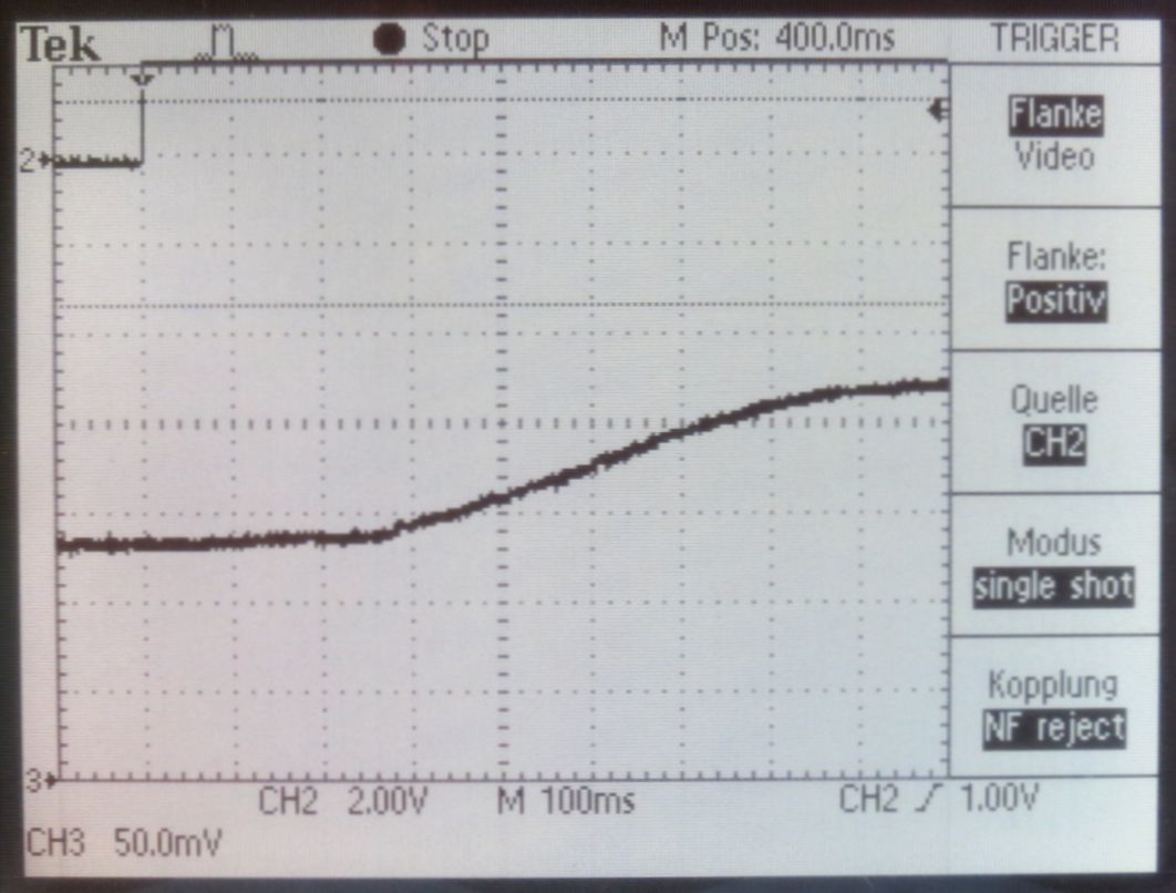
The step response data was acquired for a PWM step of 50LSB, i.e, PWM1 = 680LSB. The QR control loop rate was 312.5Hz corresponding to
Tc = 3.2ms cycle time. Using a first-order PT1-Tt plant model one finds a dead time of Tt=260ms along
with a time constant of roughly T1=100ms.
|
As expected, the delay of the drive unit is quite large, i.e, approximately 80×Tc, and limits the control loop gain significantly.
Back to main page